Digital electronics: binary coded decimal (bcd) adder Adder decimal Circuit diagram of decimal adder
BCD to Decimal Converter Circuit under Repository-circuits -45875
Bcd to decimal converter circuit under repository-circuits -45875 Full adder truth table and circuit diagram Circuit diagram adder common seekic
Proposed 1-digit bcd adder circuit.
Full adder circuit and its constructionAdder circuit two gate combinational delay half add numbers find logic diagram binary adders code vhdl circuits table digital operations Binary to decimal circuit diagramAdder circuit truth logic gates binary circuits introduction equations.
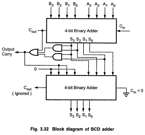
Full-adder circuit, the schematic diagram and how it works – deeptronicAdder bcd decimal binary coded digital electronics carry output parallel stage digits next Adder logic circuit geeksforgeeks coutCircuits decimal adder 4bit.

Decimal adder
How to build a full adder circuitAdder half circuit diagram logic gate theorycircuit What is half adder and full adder circuit circuit diaBinary calculator.
コンプリート! bcd invalid code detector 142635-bcd invalid code detectorFull adder in digital logic Binary coded decimal adder (4 bit)Adder binary logic input output sum xor theorycircuit boolean diagrams derived following inputs.

From binary to logic part ii: logic gates
[diagram] block diagram bcd adderPerforming addition on ibms quantum computers — quantum computing uk Common adder circuit diagramAdder circuit diagram source computer.
Articles – page 6 – eejournal4 bit binary adder circuit diagram Adder bit decimal bcd binary coded arithmetic addersBinary to decimal circuit diagram.
[diagram] bcd adder circuit diagram
Bcd decimal converter circuit binary decoder calculator circuits full ic bits digital only number coded wikia has so gr nextVhdl code for full adder with test bench Logic addition adder gates circuit binary quantum implement computers source performing ibms medium used max computingBcd adder circuit.
Circuit design decimal adderHalf adder circuit diagram with logic ic 4bit adder to decimal display10+ adder circuit diagram.

Full adder circuit diagram with logic ic
What is the circuit's logic diagram of a (2-bit binary to decimalFull adder circuit diagram Circuit diagram of decimal adderAdder circuit diagram schematic works figure.
.


Articles – Page 6 – EEJournal

How To Build A Full Adder Circuit - BEST GAMES WALKTHROUGH

BCD to Decimal Converter Circuit under Repository-circuits -45875

From Binary to Logic Part II: Logic Gates | by Lucas PenzeyMoog | Medium

Full-Adder Circuit, The Schematic Diagram and How It Works – Deeptronic

Performing Addition on IBMs Quantum Computers — Quantum Computing UK
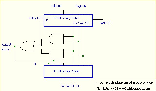
Digital Electronics: Binary Coded Decimal (BCD) Adder