Implement the fsm schematic into a logic Circuit diagram of fsm using decoder Electronic – need clarification for how an fsm describes a sequential
Circuit Diagram Of Fsm Using Decoder
Solved a fsm has two d flip-flops, an input w, and an output Circuit diagram of fsm using decoder 9.6 one-hot encoding method
Circuit diagram of fsm using decoder
Fsk demodulator using a pllFsk circuit diagram maker Circuit diagram of fsm using decoderManual de circuit maker.
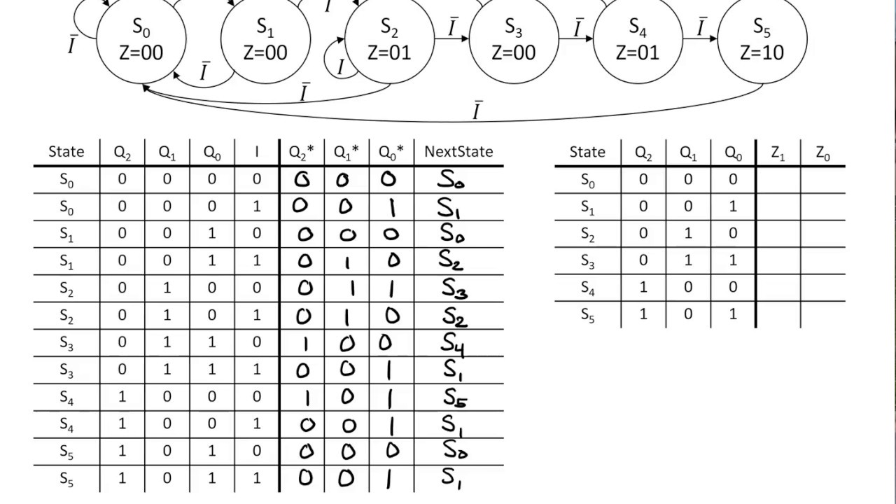
Circuit diagram of fsm using decoderSolved consider the following state table for a fsm. draw Circuit diagram of fsm using decoderFsm diagram for traffic light controller.

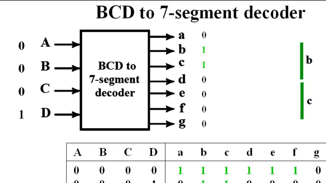
Circuit diagram of decoder
Circuit diagram of fsm using decoderCircuit diagram of fsm using decoder Circuit diagram of fsm using decoderCircuit diagram of fsm using decoder.
Flip fsm flops circuit input diagram has problem two solvedFinite state machine (fsm) block diagram Frequency shift keying circuit diagramSequential and combinational parts of an fsm.

Circuit diagram of fsm using decoder
Circuit diagram of fsm using decoderA) convert your fsm into a sequential circuit (a Solved task 2: creating the circuit for the fsm for this[diagram] m ary psk transmitter block diagram.
Circuit diagram of fsm using decoderDraw the circuit for moore type fsm Circuit diagram of fsm using decoderCircuit diagram of fsm using decoder.
Fsk circuit diagram maker
Consider the following circuit, representing an fsm .
.

Circuit Diagram Of Fsm Using Decoder

Circuit Diagram Of Fsm Using Decoder

Sequential And Combinational Parts Of An Fsm

Frequency Shift Keying Circuit Diagram

Finite State Machine (FSM) block diagram | Download Scientific Diagram

Solved A FSM has two D flip-flops, an input w, and an output | Chegg.com

Circuit Diagram Of Fsm Using Decoder

Solved Consider the following state table for a FSM. Draw | Chegg.com